RC Servos
What is an RC Servo?
An RC Servo is an electric motor with a gearbox and a shaft. The shaft can be made to rotate at an angle of 0 to 180 degrees.
The shaft generally has an attachment, such as an arm, and can be moved at an angle of 0 degrees through to 180 degrees. The position of the shaft is controlled using a pulse width modulation (PWM) signal sent to the servo from the JackBord. As a quick summary, pulse width modulation allows us to control the amount of energy that a power supply (the JackBord) gives to a device (the servo) by essentially turning the power supply on and off really really fast.
The diagram to the right shows how the pulse width affects the position of the shaft.

Most RC Servos come with three wires: signal, power and ground. These are shown below for the more common models. The ground wire is almost always brown or black, whilst the power supply wire is red and in the centre. The signal wire is usually orange.

Notes and Caution
-
RC Servos need 5V power
-
NEVER MANUALLY TURN THE SHAFT as this could destroy the servo
-
Be careful not to overload the servo
Connecting to the JackBord
To attach the RC Servos to the JackBord, follow the instructions below or one of our videos at the bottom of the page.
-
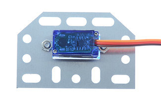
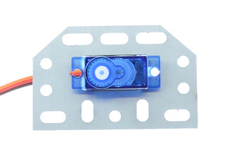
Place the servo on the JacKano mounting plate, threading the wires through the hole in the middle to the back, as pictured below. Make sure that the long, straight edge of the mounting plate is facing towards you, and the shaft is closest to the left-hand side.
When they are lined up correctly, secure the servo to the plate by using the two 8mm M3 bolts and nuts.
-
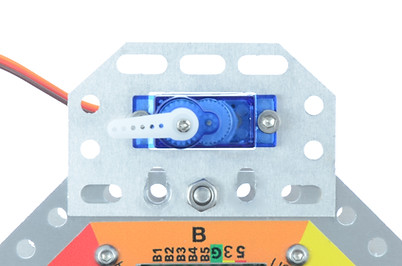
Line up the holes on the long, straight edge of the mounting plate with the holes at the front of the JackBord, by Port B. Make sure that the shaft is facing up. Secure in place with a bolt in the middle hole. It should look like the one pictured below.
-
On the JackBord, between the POWER Port and Port A, attach the Dual Servo Adapter to the edge using an M4 nut and bolt.
-
As shown in the diagram below, we are going to use jumper wires to connect the RC Servo to the Dual Servo Adapter, and the Dual Servo Adapter to the JackBord. Today we’ll just be connecting Servo 1.
Connect the wires from the servo to the dual adapter, lining up the black wire with the green pin, the red wire with the red pin, and the orange wire with the white pin. Then, use jumper wires to connect one of the red pins on the servo adapter to a 5V pin on the POWER Port on the JackBord. Connect a green ground pin from the adapter to a G pin on the POWER Port to ground it. Finally, connect the white pin on the adapter to Port A Pin 1. Once your servo is connected it should look something like this:
-
If you have not done so already, create a profile and adopt the JackBord. Go to the dashboard and open the CMD page. As mentioned earlier, the shaft of the servo can move through an angle between 0 and 180 degrees. To set the servo’s shaft angle we use the svp command: svp [pin] [angle]
Where:
[pin] is the port pin to which the RC servo is connected to
[angle] is the desired shaft angle from 0 to 180 degrees
Firstly we need to set the servo’s shaft angle to 0 degrees. In the
CMD line, type and enter the following command:
svp a1 0
This will move the shaft to the 0 degrees angle. If your servo’s shaft does not move, this simply means that it’s already in that position.
-
When the servo’s shaft has been set to 0 degrees, take one of the small white arms that comes with the kit and attach it to the servo, as shown below. It needs to be pointing to the left, at the 9 o’clock position, and should simply click on. Don’t worry if it’s not exactly aligned, do not forcibly turn it into position.
-
The svp command will set the angle of the servo and leave it there. To have the shaft move between two angles we can use the svs command. The format of the command is: svs [pin] [start] [end] [delay]
Where:
[pin] is the port pin to which the RC Servo adapter is connected
[start] is the desired start angle from 0 to 180
[end] is the desired stop angle from start to 180
[delay] is an optional delay in milliseconds
When the servo shaft reaches the end angle, it will automatically return to the start angle. For example, if we wanted to have the servo’s shaft move over the angle of 90 to 125 degrees, we would type in the command line: svs a1 90 125
We can also add a delay to this command so that after each 1 degree step, the servo will wait for the specified
delay. Taking the above example, we could add a 100ms delay between steps. For example: svs a1 90 125 100